Monthly Archives: January 2017

Hunter Node Irrigation Control

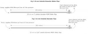
What is a Hunter Node

The Hunter Node was first introduced by Hunter Industries in 2012.  The Hunter Node is a 9 volt battery power control unit that can be used to operate any size Hunter Valves using a 9 volt dc latching solenoid The Hunter Node is available as 2 options.  A Hunter Node 100 which comes with the Hunter solenoid valve and the Hunter 400 which can control up to 4 valves however the valves have to be purchased as a separate item.

When Would you Use A Hunter Node

In most situations we would suggest that you use the industry standard 24 volt ac valves with a mains powered control unit.  These are by far the cheapest and most reliable method of controlling your irrigation system.  However there are occasions when this is not possible.  As an example a remote location on a gold course or garden or sometimes the inconvenience that is associated with installing a low voltage lead to a valve box after landscaping has been complete.  In these situations the Hunter Node is ideal.  The valve is installed in to the line that needs to be controlled and after a few key clicks it is ready to run.

What Is The Difference Between The Hunter Node 100 and 400

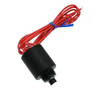
The Hunter Node 100 comes complete with the solenoid valve.  This is pre wired and pre fitted ready to thread in to any Hunter Solenoid valve.

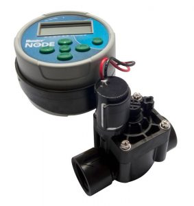
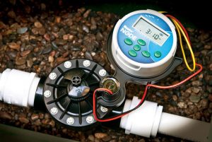
The valve once installed is compact and very easy to operate

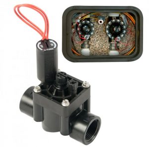
The Hunter Node 400 is used to control any number of valves up to 4.  The 400 is just the control unit and to this you would need to add the valves with the dc solenoids.  The example below is operating three of the Hunter 1″ BSP valves

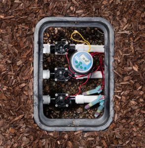
In Order for the above to operate you would have to purchase in addtion to the control unit

Three Dc Latching Solenoids and three valve bodies

Porous Pipe Compared To Pressure Compensated Leaky Hose

Porous pipe

Porous pipe or leaky pipe that looks like rubber with lots of holes in is made from recycled tyres along with other material.  The pipe drips along its entire length however there is no control or calculation that can be put on the pipe as the drip is very random because of the nature of the pipe.  What this means is that we cannot be sure how much can be used before the water pressure falls below a certain level which would then leave the pipe dripping at the beginning of the pipe but with little or no water dripping out at the far end.

When porous pipe is used with hedging over a long length we can see after a few years the erratic dripping as the hedge grows at an erratic speed with plants near the source receiving more water than those at the end of the pipe.

Porous pipe drips along its entire length which again is not the ideal as water spreads under the soil surface and so to much water is applied over the length of the pipe.

Porous pipe can clog easily and this again leaves us with erratic watering patterns that can leave areas totally dry

Pressure Compensated drip pipe. 

Unlike porous pipe pressure compensated drip pipe leaks at a uniform rate.  We can apply calculations to the pipe and know for certainty how much water is being applied per square metre.  We know that the same amount of water will be applied to the first and last plant in the run.  With pressure compensated drip pipe we know that the volume of water applied to the bed , border or hedge will not fall along the run.  Pressure compensated drip pipe leaves the majority of the soil surface dry which reduces the amount of evaporation and reduces the amount of annual weeds that can germinate.  Pressure compensated drip pipe has had years of research and development put in to the product and is the most used drip pipe Worldwide because it can be used commercially with confidence


What Is The Difference Between A Pressure Releif Valve And a Pressure Regulator

A pressure releif valve is a valve that will open when the pressure exceeds a certain level and once open will allow water to bypass the system and return the water to the tank. These are installed in very high pressure systems and will protect the pipe and equipment etc.  They will protect pumps as they will make sure that water continues to move through the pump even if a fault occurs that prevents water from running ie a valve fails to open and the pump would eventually start boiling the water in the pump causing permanent damage


A pressure regulator will regulate the pressure on the outlet of the regulator and make sure that the pressure does not exceed the pre set amount. So the regulator will make sure that any equipment connected to the outlet of teh regulator is protected however pressure will be build up on the inlet

What Size Pipe Should I Use For My Pop Ups

What happens when water is pushed through up water pipe

The correct pipe diameter is decided based on the amount  the volume of water being used or the flow through the pipe. When water is pushed along a pipe friction is created. The amount of friction depends on the speed the water the water needs to move along the pipe in order to supply the volume of water at the outlet.  This loss in flow is called friction loss.  There are other factors that will contribute to flow and pressure loss, as an example elbows etc however for this example we will assume a straight run with no connectors

How large is the variation

In the example below we will assume that we are going t be using 2500 litres per hour at the outlet and that the total length of the pipe is 100 metres.  We will assume that our pump is delivering 4500 litres per hour in to the pipe at 5 bar pressure

In figure 1 we are supplying 4500 litres per hour at 5 bar pressure and we have opened the tap to allow 2500 litres per hour to exit.  In order for the 2500 litres per hour to exit the pipe the water will move with a velocity of 1.9 metres per second.  Velocities at over 1.5 metres per second should always be avoided as this can cause water hammer.  Over the 100 metre length we will see a loss of 2.16 bar pressure due to the internal friction of the pipe.  So the pressure at the exit would = 5 – 2.16 = 2.84 bar.


In Figure 2 we are supplying exactly the same amount of water at the same pressure however the external pipe diameter is now 32 mm and the pipe wall thickness is exactly the same.  In order to supply the 2500 litres per hour at the outlet the water will need to travel at 1.1 metres per second.  The friction loss in the 32 mm pipe is 0.54 bar over the 100 metre length so our outlet pressure will be 5 – 0.54 = 4.46 bar.  From this we can see that with a slight change in pipe diameter we have a huge energy saving.

If we were to increase the diameter of the pipe to 50 mm we would see a 0.19 bar pressure drop based on the above figures making this the most efficient option however cost wise it would not be the prefered choice, the 32 mm dimeter pipe would be the prefered option.

What size water pipe should I use

You now having an understanding of what happens when you run water through a water pipe.  From this information you can now decide on the diameter required however there are numerous other variable that will change your calculations, for example elbows, turns, type of pipe and wall thickness of the pipe.  Our advice is to email us at [email protected] or call us on 01189736905 so that we can calculate your requirements preventing expensive and time consuming mistakes